Emergency LED light circuit
Here is a simple LED emergency light circuit that you can
implement for home lighting during power failures. We know that LED
bulbs consume very less power and hence they have a much longer life.
This led lighting circuit design is intended to light automatically
during main power failures.
So here we are going to help you with the building of cheap emergency lights. The main part of this led lighting circuit is a relay, which automatically connects DC voltage to the battery when main power is present and connect LEDs to the battery in the absence of main power supply.
Components Required
- Step down transformer-1 (230V to 12V or 110V to 12V)
- Diodes-5 (1N4007)
- Capacitor-1 (470µF)
- Led-1 (Red)
- Resistors-2 (1K)
- Relay-1 (12V)
- Rechargeable Battery-1 (12V)
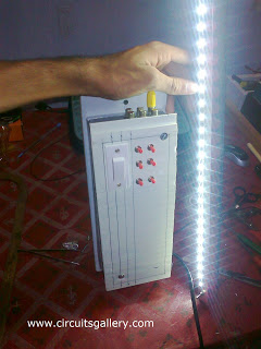
- Switch LED Array (Group of LEDs, See my prototype )
- Also see: Remote controlled lamp circuit
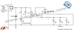
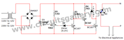
- The step down transformer and the bridge rectifier steps down and convert the high AC (in the range of 110V or 230V) voltage to low (12V) DC voltage.
- The diode D2 prevents the battery charge from flowing back also it acts as a free wheeling diode too.
- In the presence of electricity, the relay contact connects the NO (Normally open) terminal to battery. Thus battery charges during this time.
- We are using a Red LED as the charging indicator which glows when the emergency light battery is charging.
- When supply failure occurs, relay connects the NC (Normally Closed) terminal to the battery.
- The LED arrays are connected to NC terminal, thus they glow by using the charge stored in the battery.
2.Simple fire alarm- thermistor circuit diagram
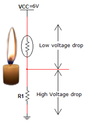
Here i-St@r comes with a simple and automatic fire alarm and detection system. This fire detection alarm circuit is based on thermistor, what is a thermistor? A thermistor is nothing but a variable resistor whore resistance increases as temperature decreases. Fire detection is simply possible via this low-cost alarm circuit.
A simple potential divider arrangement using thermistor is capable of sensing the temperature (presence of fire) and alerting us with a warning signal. This firealarm circuit is suitable for your home security systems. Also school students can do this fire detector circuit as their high school science fair projects. Here we explained in detail about fire alarm circuit wiring and animation/ simulation of fire alarm.
Components required
- Power supply
- Resistors ¼ watt (470Ω; 33kΩ)
- Capacitor (10µF, 16V)
- BC548 transistor
- Thermistor
- Diode (1N4001)
- 6V Buzzer
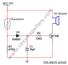
- Working of this simple fire alarm circuit is based on switching property of transistor.
- The thermistor and R1 forms a potential divider network which drives the transistor.
- The heart of this circuit is a thermistor, what is a thermistor? Thermistors are low-cost, easily-available temperature sensors. Thermistors are widely used for uncomplicated temperature measurements.
- Thermistors are temperature sensitive resistors. When temperature increases resistance offered by the thermistor decreases and vice versa. At normal temperature, the resistance of the thermistor is around 10kΩ.
- All resistors vary with temperature, but the semiconductor materials used for thermistors are especially sensitive to temperature.
- The transistor is turned ON by the voltage drop across the resistor R1.
- Consider the temperature of the atmosphere is around 25°C, and then the resistance of thermistor is high so the voltage across the thermistor is also high according to the basic ohm’s law V=IR.
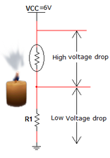
- At this situation voltage across resistor R1 is low and it is not sufficient to turn on the transistor.
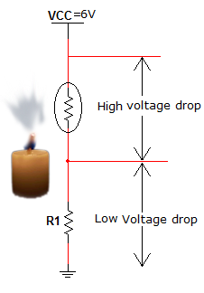
- As temperature rises, the resistance of thermistor decreases so that
the drop across the resistor R1 increases which turn ON the
transistor.
- When the transistor is turned ON, the current from Vcc starts flow via the 6V Buzzer which produces beep sound.
- Diode used for enabling unidirectional conduction and the capacitor removes sudden transients from the thermistor.
3.UM66 Musical door bell alarm circuit- Melody generator
This circuit is suitable for Musical bell for door, home security alarm
systems, burglar alarms etc. The main part of this alarm circuit is
UM66, it is a melody generator IC. It is very small almost looks like a
transistor, it has an inbuilt tone and a beat generator. The IC
is programmed to generate certain frequencies.When power is turned on,
the melody generator is reset and melody begins from the first note.
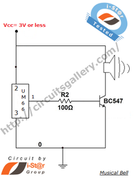
Many versions of UM66T are available which generate tone of different songs. The power (Vcc) should not exceed 3V it may leads to the damage of UM66 IC. If you want to this circuit to other circuits sharing a common Vcc which is grater than 3V Zener diode voltage regulator can be employed. This is a very simple battery powered melody generator circuit. Feel free to leave a comment in the comment box below for any doubts.
Many versions of UM66T are available which generate tone of different songs. The power (Vcc) should not exceed 3V it may leads to the damage of UM66 IC. If you want to this circuit to other circuits sharing a common Vcc which is grater than 3V Zener diode voltage regulator can be employed. This is a very simple battery powered melody generator circuit. Feel free to leave a comment in the comment box below for any doubts.
Components Requiered
- UM66 Musical IC
- Resistor 100Ω
- Transistor BC547
- Speaker
- 3V Battery
- When power is switched On, UM66 starts to generate the melody current.
- The output from the UM66 IC has no sufficient power in order to drive a speaker. So we are using an NPN transistor as an amplifier.
- The operating voltage of UM66 is 1.5V to 3V. The supply voltage should not exceed 3V, If is happens, the IC will damage.
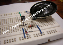
- Here is the assembled form of above circuit in i-St@r Lab. The Zener diode is used for protecting UM66 from high voltage
4.SIMPLE OVER VOLTAGE PROTECTION CIRCUIT: HIGH VOLTAGE CUT OFF
Voltage fluctuation is a serious issue in every home. Due to some
reasons our supply voltage may rise above 110V or 230V. Flow of this
high electricity may leads to the damage of our home electrical devices.
Have you thought how electrical protection is possible via a simple over voltage protection circuit? Here CG comes with an interesting over voltage protection device to protect your electrical appliances from high voltage. Zener diode voltage regulator is the main part of this high voltage cut off circuit. You can implement this over voltage protection relay circuit in your home as a high voltage regulator.
Components required
- Transformer (110V to 12V or 230V to 12V)
- Diodes (1N4007 x 5)
- Zener diode (6.2V)
- Capacitor (1000µF, 25V)
- Resistors (5.6kΩ; 6.8kΩ; 1kΩ)
- Potentio meter (10kΩ)
- Transistors (BC187 x 2; BC547)
- 12V relay
- R1 and R2 forms a potential divider network, we can adjust the cut off voltage by varying the 10K pot (R2).
- Neutral line is directly connected to the ‘Common’ terminal of relay, then the ‘NO’ terminal and Phase lines are fed to the home appliances.
- Q3 is always in ON state, so the relay connects the electrical appliances to the mains.
- At normal condition a small amount of current will flow through the zener diode but it is insufficient to turn ON the transistor Q1.
- Sudden increase of supply voltage (over voltage) leads to the increase of zener current. This current will turn ON the transistor Q1.
- The collector voltage of Q1 is applied to the base of Q2. Thus Q2 and Q3 become OFF because, transistor acts a digital switch here.
- Q3 is our relay driver, turning OFF of Q3 shuts down the relay too.
When relay is OFF, there will be no supply of electricity to the device.
Hence they protected from over voltage.
5.Water tank overflow liquid level sensor alarm circuit
Water tank overflow liquid level sensor alarm circuit is a simple electronics project for school students. In the previous articles we had discussed about Numeric water level indicator and Water level controller circuit but those circuits are much complex and are advanced projects for engineering students. The circuit schematic for Water tank over flow alarm is shown below. It produces a beep sound when the water tank is completely filled by water.
The advantage of this project circuit is that it saves water from accidental over flow. The circuit simply consists of a liquid (water) level sensor or water level detector with BC547 transistors. Any electronics hobbyist can implement this water tank over flow alarm at your home or work places at a cheap rate ($0.5). The heart of this water over flow circuit is the Transistor switching part.
So this circuit always prevents the wastage of water when you forget to switch OFF the motor pump set after switch ON
Components required
Simulation of water tank level sensor alarm
The advantage of this project circuit is that it saves water from accidental over flow. The circuit simply consists of a liquid (water) level sensor or water level detector with BC547 transistors. Any electronics hobbyist can implement this water tank over flow alarm at your home or work places at a cheap rate ($0.5). The heart of this water over flow circuit is the Transistor switching part.
So this circuit always prevents the wastage of water when you forget to switch OFF the motor pump set after switch ON
Components required
- Power supply
- Resistors ¼ Watt (1kΩ x1, 100Ω x2)
- Transistors (BC 547 x 2)
- 6V Buzzer
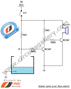
- Water over flow from a tank or reservoir is detected using this simple project circuit. Close switch SW to turn on the device.
- Initially the potential at point A in the circuit is Vcc so the transistor Q1 remains in ON state (Read transistor act as a digital switch), and its collector voltage at Vce sat (0.02V).
- The collector voltage of Q1 is fed to the base terminal of transistor Q2 via100Ω resistor.
- 0.02V is not sufficient to turn on the transistor Q2 hence it remains in OFF state and the Buzzer will not produce any sound.
- A connection from ground is dipped in the water reservoir. When water level rises, the ground comes in contact with the base terminal of transistor Q1. Thus it changes to OFF state and the collector voltage rises to Vcc.
- The high voltage at the collector of Q1 turns ON the transistor Q2 since this high voltage is connected to the base of transistor Q2, then a current flow occur though the Buzzer circuit and it produces beep alarm sound. (Read transistor act as a load switch)
- See the simulation window below, instead of Buzzer circuit we have used an LED for simulation. The switch ON being similar to water touching the point A.
Simulation of water tank level sensor alarm
6.Simple battery charger circuit and battery level indicator with low battery recharge alarm
This is a simple circuit of 12V rechargeable smart battery charger circuit.
You can use this best battery charger circuit as car battery chargers,
Inverter battery charger, Emergency battery charger etc. Automatic
indicator alarm circuit is also comes along with this battery charger schematic. The main advantage of this indicator is that a buzzer informs us when the battery needs recharge. This circuit schematic definitely helps for your daily life battery charging applications.
Components required
Components required
- Transformer (230V to 15V or 110V t0 15V)
- Bridge rectifier (1N4007 x 4)
- Capacitor (470µF, 50V)
- Voltage regulator IC 7815
- 12V rechargeable battery
- Diode (1N4148)
- LED Zener diode 9V
- Transistor (BC547 x 2)
- Resistors (10kΩ, 1.5kΩ, 100kΩ Each ¼ Watt)
- Buzzer (12V)
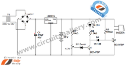
- The charging circuit is build around voltage regulator IC 7815 and two transistors BC 548.
- The main supply 230V or 110V is step down using a step down transformer, and then it is rectifiered and filtered out.
- That DC voltage is fed to the voltage regulator IC 7815; the output will be regulated 15V.
- 12 volt rechargeable battery is connected at the output of voltage regulator and it charges when main power is available.
- This circuit indicates the charging status that is the LED1 is glows when the battery charged (Above 10.5V).
- When battery voltage goes below a particular value LED1 stops glowing and the buzzer produces sound indicating that the battery has been discharged and it needs recharge.
